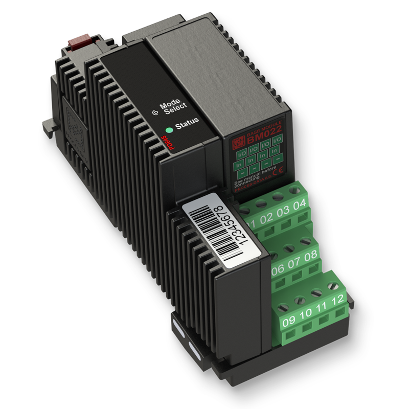
Product Description
PD 645 can be configured in several different configurations to accommodate various analog input- and output functions.
In the following sections, a brief description is given for eachof the possible functions.
Analog output
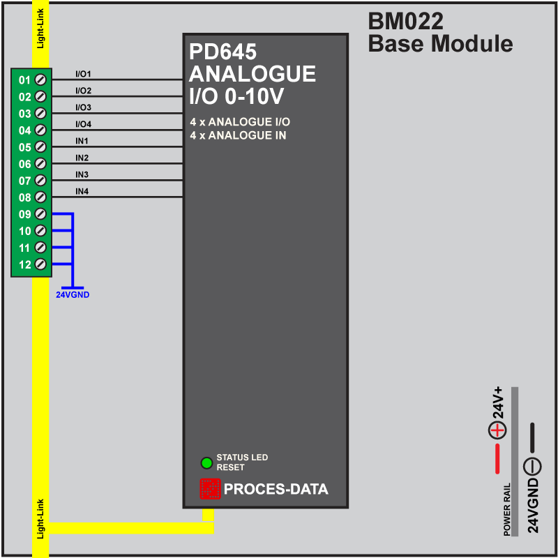
Each channel in the PD 645 can be configured as an analog output, which means that the PD 645 supports running 4 channels of analog output simultaneously.
In this configuration, the output voltage is between the (I/O) terminal and the (-) terminal.
The output is monitored and can read back the output voltage, as well as report if excessive current is being drawn from the output during operation.
Analog input
PD 645 can have all 4 channels configured as analog inputs.
In this configuration the PD645 measures the voltage between the (I/O) terminal and (In) terminal as a differential measurement.
Having this measurement being differential, allows precise voltage measurement even from devices that produce ground
potential differences between the PD 645 and the device you wish to measure an output from.
If a single ended measurement is required, the (In) terminal must be connected to the (-) terminal and use the (I/O) terminal as input.
This will result in the voltage to be measured between the (I/O) and the (-) terminal.
Potentiometer interface
PD 645 can be configured to read up to 4 potentiometers, one per channel. In this configuration, the PD 645 supplies the voltage
to the potentiometer with the (I/O) terminal, and is fully adjustable.
The (In) terminal reads the voltage on the wiper of the potentiometer, referenced to the (-) terminal.
This configuration has read back of the applied voltage to the potentiometer, and can report if excessive current is being
drawn from the output during operation.
The PD 645 can combine up to 4 of the above-mentioned functions at the same time.
For example, you could have 2 potentiometers connected, 1 analog output and 1 analog input, at the same time, in a single PD 645.
SPECIFICATIONS
Analog input
Input signal range………………………………………………. -2 to 12 V
Calibration error @ Tamb. 20 °C……..Max +/- 0.1% of full scale
Temperature coefficient Tc …………………… Max +/- 50 ppm / K
Resolution………………………………………………………………..1 mV
Accuracy…………………………………………………………………..5 mV
Input impedance………………………………………………. Typ. 86 kΩ
Analog output
Output signal range……………………………………………..-1 to 11 V
Calibration error @ Tamb. 20 °C……Max +/- 0.05% of full scale
Temperature coefficient Tc……………………. Max +/- 80 ppm / K
Resolution……………………………………………………………..0.5 mV
Accuracy…………………………………………………………………..1 mV
Short circuit current @Tamb. 20 °C……………………. Typ. 18 mA
Continuous current per channel………………………..Min. 10 mA
Sink current per channel………………………………….Min. 2.5 mA
Power specifications
Supply voltage nominal………………………………………….. 24 VDC
Supply voltage range……………………………………… 12 to 32 VDC
Typ. Internal power consumption (@ 24 VDC)…………….. 0.8 W
Max power consumption (@ 24 VDC)………………………….1.6 W
Environmental conditions
Operational temperature …………………………… -25 °C to +70 °C
Storage temperature…………………………………. -40 °C to +85 °C
Relative humidity …………………………….. < 95% RH (non-cond.)
Protection class…………………………………………………………. IP40