Delay rules for P-NET

P-NET, 4-WIRE P-NET and P-NET Light-Link
To achieve an efficient network, P-NET specifies rules for bus traffic timing. When a P-NET device sends out a request, the response must arrive back within a specified time.
Delays in the transmission are created by the signal propagation time in the cable and delays in repeaters and conversion from cable to Light-Link.
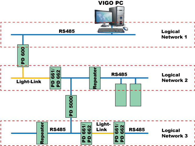
Only communication between devices on the same logical bus is affected by such time delays. As soon as the signal is routed through a multi-port device, a new logical network is reached.
Example of logical networks in an installation:

A delay is measured in “bit times”, Tbit.
A Tbit is the time used to signal one bit on the bus.
With a communication speed of 76.8 kbit/s, a Tbit is equal to 13μSec.
Maximum allowable delays:
– Between any masters: 2 Tbit.
– Between any master and slave: 6 Tbit.
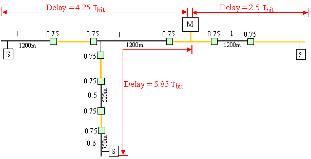
If a logical network contains only 1 master (Single master system), the maximum delay from the master to any slave on the network is 6 Tbit.
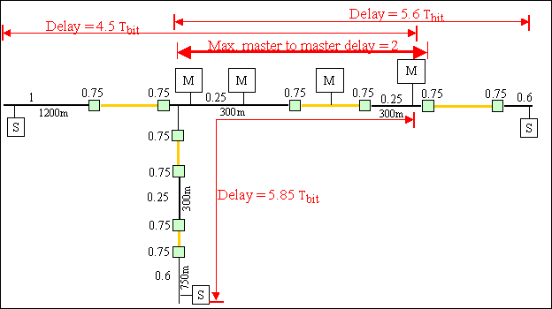
If a logical network contains more than 1 master (Multi-master system), the maximum delay between any two masters is 2 Tbit, and the maximum delay between any of the masters and any slave is 6 Tbit.
Delay calculation
Delay in cable
Each 125 metres of bus cable adds 0.1 Tbit.

Example: 200 metres of cable introduces A / B delay = (200/125)*0.1 = 0.16 Tbit
Delay in repeater (PD 3280 / PD 3285)
Each repeater adds a delay of 1 Tbit.

Example: 200 metres + repeater + 300 metres introduces A / B delay =
(200/125)*0.1 + 1 + (300/125)*0.1 = 1.4 Tbit.
Delay in Light-Link (M36)
Each conversion between P-NET RS485 and P-NET Light-Link adds a delay of 0.75 Tbit.
Light-Link cable and Light-Link modules do not add any significant delay.
Example: 200 metres + PD 661 + Light-Link + PD 661 + 50 metres introduces A / B delay =
(200/125)*0.1 + 0.75 + 0 + 0.75 + (50/125)*0.1 = 1.7 Tbit.
When using a redundancy P-NET installation, it is essential that both RS485 networks are symmetrical with respect to delay. The maximum delay asymmetry of the two redundant networks is: 0.5 Tbit.
The difference in the length of the two redundant network cables must not exceed 600 metres.
Network delay examples
Single master system

Multi-master system

In a multi-master system; no more than 1 Light-Link section and 600 metres of cable is allowed between any 2 masters.
Signal propagations calculation
A bit time is the time used to signal one bit on the bus. With a communication speed of 76.8 kbit/s the bit time is equal to 13 μSec.
Cable signal delay calculations:
Belden cable:
Light speed = 300.000 km/s. Signal propagations 75%
Effective signal speed = 225,000 Km/s.
1200m produces a delay of: 1.2 / 225,000 = 5.3 uS ~ 0.4 bit time, in each direction.
1200m total delay = 0.8 bit time (request delay + response delay).
0.1 bit = 1.3 uS = 292 m (145 m total)
(IBM Twinax):
Light speed = 300,000 km/s. Signal propagations 66%
Effective signal speed = 198.000 Km/s.
1200 m adds a delay of 1.2 / 198,000 = 6.1 uS ~ 0.5 bit time, in each direction.
1200 m total delay = 1 bit time (request delay + response delay).
0.1 Bit = 1.3 uS = 250 m (125 m total)


