Application note
PD 662 Redundancy Interface notes
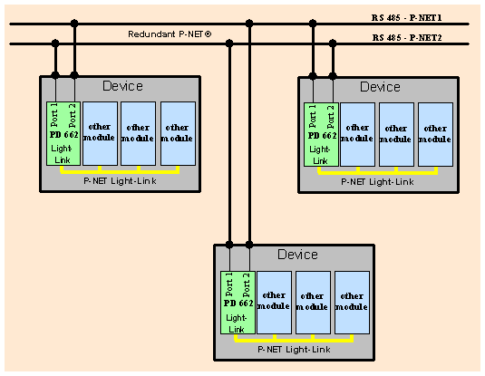
Including a PD 662 as a component within a cluster of modules forming a device provides the ability to create a redundant P-NET link between a number of devices.
The redundancy is accomplished by connecting all devices together using 2 independent P-NET networks.
This means that if one of the alternatively routed networks fails, it will not have any effect on overall system operation.
Block diagram showing principle of redundancy system:

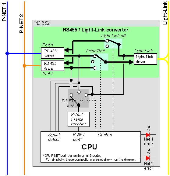
Functional block diagram of PD 662:

Normal operation
Two events are possible: A signal arrives on the RS 485 side or a signal arrives on the Light-Link side.
When a signal arrives on the RS 485 side, the same signal is received on both RS 485 ports. Depending on the ActualPort switch, one of the two signals is passed to the Light-Link port.
A signal received on the Light-Link port is always transmitted on both RS 485 ports.
The signal detection system switches the ‘P-NET test’ switch to the position to allow the PD 662 to listen to the frame passing through. The frame is analysed for errors. If the frame is an actual request to this PD 662, a response is created and sent out on all three ports.
If the signal arrives on the RS 485 side, the ‘P-NET test’ switch connects to the active port to receive and analyse the frame.
To ensure that the redundant RS 485 port is in good condition and ready to take over in the event that the active port should fail, each 5th frame is taken from the redundant port and analysed.
In normal operation, the same signal arrives on both Port 1 and Port 2. When receiving on the RS 485 side, the two signal detection inputs are compared to ensure both networks are operational.
Preferred Port
By Preferred Port, it is possible to make the PD 662 use a specific port as ActualPort whenever that port is OK. The redundant port is only used during the period of time when the Preferred Port is in error state.
If no Preferred Port is specified (auto), the PD 662 selects port 1 as ActualPort at power-on. If the ActualPort fails and the redundant port is OK, the PD 662 switches to use this and stays on this port as long as it is OK.
Frame error analyse
A P-NET packet consists of several bytes. When the P-NET packet is copied into the CPU via the ‘P-NET test’ switch, it is analysed for framing errors (error on the individual byte frames) as well as P-NET frame errors such as checksum, size and syntax. (See error flags).
Error Rate
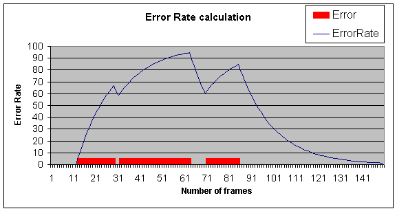
The PD 662 continuously calculates an error rate indicator for each port. Error rate is shown as a number from 0 to 100. It is a non-linear calculation that favours the tendency of frame quality.
A few consecutive errors will have a high impact, whereas it takes a high number of good frames to settle back to 0.

(see Error rate formula)
Port status
Each port has a frame status buffer that contains the status of the last 16 consecutively analysed frames from that particular port.
If the count of frames with an error status gets higher than the defined maximum (ErrorMax), the port status is changed to an Error state.
ErrorMax can be adjusted in the range of 1 to 8. Factory setting is 5. It is normally not recommended to set ErrorMax to a value below 5, as this may result in problems to re-connect (synchronise) two network sections that had be disconnected by a PD 662.
When the port is in an Error state, the received frames are still analysed, and the buffer is still updated. When the port again receives valid frames and the error status count falls below ErrorMax – 2, the port status is changed back to the active port.
Example: ErrorMax is set to 6. When more than 6 out of 16 consecutive frames are erroneous, the port is set to the error state. When in the error state, the port must receive less than 4 erroneous frames within 16 consecutive frames to change the port status back to active.
The Status of each of the two RS 485 ports are shown on the LEDs. When a LED is ON (RED) the corresponding port is in the error state. When the LED is OFF, the port is in the active state.
Error flags
The ErrorFlagsAct (Actual error) flag array is updated when the port status is changed to an error state. When changing to an error state, the bit for all error types represented within the last 16 analysed frames is set. When the port is OK and the status is changed to an active state, all bits in ErrorFlagAct are reset.
ErrorFlagHis (historic error) is updated with copy of the ErrorFlagAct when the port changes to an error state. When the port is OK and the status is changes to an active state, the ErrorFlagHis remains unchanged until reset by the user, and will therefore show the historic reasons for the error state.
Error counters
For each port, 4 error counters exist. The error counters are incremented for each analysed frame with the corresponding error type. (see error flags)
The counters count from 0 to 255. Each counter is initialised to 0 at power-up, and stops counting when it reaches 255.
These counters can be used as a diagnosis and validation tool: At any given time the counters can be manually set to zero. At a later stage, the counters can be read out to show the statistic for each type of error.
RS 485 Ports in error state
When one RS 485 port is in an error state while the other port is used as the active port, the ‘P-NET test’ still switches to the port in error. This is done in order to detect when the port is again back in operation.
When the ‘P-NET test’ is switched to the port in the error state and the frame passing through is an actual request to this PD 662, no frame will reach the CPU and therefore no response will be sent back. The requester will see this as a “no response”.
This “no response” only relates to requests to the PD 662 itself. All frames are still passed through the PD 662 allowing all other slaves or masters connected via the PD 662 to respond as usual.
To reduce the number of “no response” messages, the ‘P-NET test’ switching rate is reduced to sample one frame for every 10 frames received on the active port.
RS 485 errors
for both RS 485 nets become unserviceable, the PD 662 cannot detect this error because the PD 662 will see it as if nothing is connected to the ports. This means that the input is the same on both ports and therefore no errors will be generated. If one RS 485 net has been broken and has been shut down, and then the other RS 485 net breaks, the PD 662 cannot turn off the last RS 485, because it can see nothing on the ports, and therefore no packages are arriving to detect errors on the last broken net. This means that the last port continues to indicate OK, until one of the nets has been fixed.
If both ports are OK and the one used as the active port breaks while the redundant port is still OK, the PD 662 switches immediately to use the redundant port, without waiting for MaxError to be exceeded.
Light-Link port in error state
If the ErrorFlagsAct register for Light-Link shows a Line Error, it is likely that the Light receiver is constantly receiving light pulses without pause.
When the Line Error occurs on the light-link, the PD 662 frame-check mechanism switches ‘P-NET test’ switch between the light-link and the RS 485 ports. If the PD 662 switches to RS 485 in the middle of a package, the switching may result in a frame being wrongly marked with an error. Due to this, a PD 662 may report an ErrorRate that is higher than actual on the RS 485 ports when the Light-Link is in an error state.


