Application note
PD 626 Stepper motor controller – System Notes
P-NET Communication speed on Light-Link
PD 626 supports all P-NET Light-Link communication speeds
Acceleration:
A stepper motor is normally used within an open-loop control system i.e. without any position feedback.
The position is derived by counting the number of steps performed by the motor from a known initial position.
The acceleration of a stepper motor must never be set to be faster than the available torque capability that the motor can accelerate the control object.
If a stepper in an open-loop control system is over-torqued, all knowledge about the rotor position will be lost and the system will need to be reinitialized.
The PD 626 always uses the Acceleration value for all speed changes.
Control modes:
The PD 626 can operate in two modes:
Position mode:
When the Run flag is set and the ActualPosition differs from SetPoint, the stepper will always move to the position given in SetPoint.
If the set point is lower than the actual position, the motor will reverse. If the set point is higher than the actual position, the motor will run forward.
The Acceleration value is always used for both acceleration and deceleration as well as calculation of deceleration length enabling the motor to stop at the SetPoint position.
The maximum speed required is defined by the value in PositiveSpeedLimit and NegativeSpeedLimit.
When the position setpoint is reached, the motor stops and the Run flag stays set. If a new position is now written to SetPoint, the motor will immediately perform a movement to this position.
The SetPoint can be changed while the motor is running and the system will use this as the new target position. If the SetPoint is changed to a value below the actual position, the motor first stops using the acceleration value and then reverses to the position given by SetPoint
Speed mode:
When the Run flag is set, the motor will accelerate to the speed given by SetPoint.
The controller will use the acceleration value to reach the requested speed. The speed cannot exceed the value defined in PositiveSpeedLimit or NegativeSpeedLimit.
If a new speed is entered in the SetPoint, the acceleration value will be used to change from the current speed to the new requested speed.
Whenever the target speed is reached, the motor will continue at this speed until the Run flag is reset by the DPI or by an input event.
Waveforms:
Waveform = 0
Half step forwar
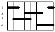
Half stepping runs the motor at double the defined resolution.
Waveform = 1
Single full stepping forward
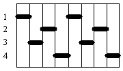
Standard operation.
Waveform = 2
Dual full stepping forward
and
2 bit gray-code signal
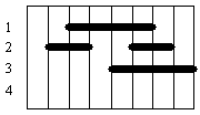
Dual full stepping produces a torque about 1.4 times greater than the single full stepping sequence while using twice as much power.
Waveform = 3
3 bit gray-code
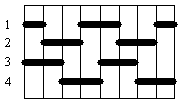
Used with some proprietary high current driver units.
Speed deviation:
Due to the resolution of the internal PD 626 timer, not all speeds can be produced exactly.
The motor will be driven at the highest possible speed that is lower than or equal to the set point.
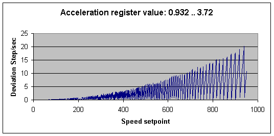
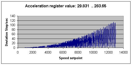
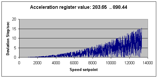
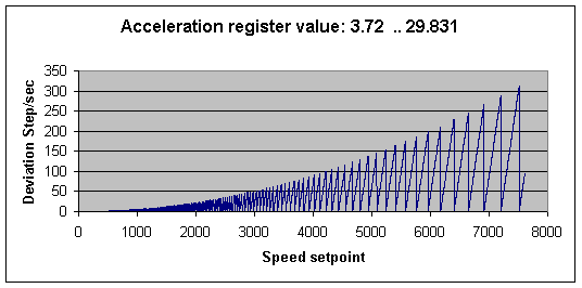
Depending on the acceleration value and the requested speed, the speed deviation value can be extracted from the graphs below.
| Minimum acceleration: | Maximum acceleration: | Minimum speed: | Maximum speed: | Timer resolution: |
|---|---|---|---|---|
| 0.932 | 3.72 | 0.66 | 892.8 | 23.5 μSec |
| 3.72 | 29.831 | 2.637 | 7159.44 | 5.787 μSec. |
| 29.831 | 283.65 | 21.10 | 13000 | 723.4 nSec. |
| 283.65 | 898.44 | 168.8 | 13000 | 90.4 nSec. |
Useful System Design Calculations
Speed at a given time:
Speed = Time x Acceleration Register².
Example: The Acceleration Register contains the value 10 and the motor has been running for 8 seconds.
Speed after 8 seconds is: 8 x 10² = 800 Step/second.
Time to reach a given speed:
Time = Speed / Acceleration Register²
Example: The Acceleration Register contains the value 10 and the motor must run at 800 steps/second.
Time to reach the speed is: 800 / 10² = 8 seconds.
Acceleration Register value needed to reach a given speed after a given time:
Example:
The target is to reach a speed of 800 steps/second after 8 seconds.
Acceleration Register =
Example:
The target is to reach a speed of 800 steps/second after 8 seconds.
Required Acceleration Register value is:
=
= 10
Useful Stepper Motor Hints
Maximum stepper speed:
Normally the maximum speed of the stepper motor is included in the data sheet of the motor.
If this data is not available, an estimate of the speed that a stepper motor can achieve, while still providing 63% of its maximum torque, can be found by dividing the resistance (R) with the inductance (L).
The resistance is the sum of the motor’s internal resistance and the external current limiting resistor, if any. The inductance is the motor’s internal coil inductance.
Example: If a motor has a winding resistance of 75 ohms and an inductance of 30 mH, the working speed before “torque drop off” would be 2500 steps/sec. If additional external “current limiting” resistance is added to an increased voltage power supply, the working speed will increase in proportion. Example: Add a 75 ohm external resistance and increase the supply voltage by two. Speed = 150 / 0.03 = 5000 steps/sec.
Stepper torque:
Stepper motors specify their torque capability as their main characteristic. Torque is a measure of the ability of the motor to turn an object and can be thought of as a lever of certain length being applied to the object with a certain force being applied to it. It is calculated as Force (Newtons) x Distance (Metres) x Sine (angle of force).
If the force is perpendicular to the lever (90 deg), Sine 90 = 1.
The force of 1 Newton can be regarded as equivalent to a weight of 100 g. being applied.
Example: The holding torque of a stepper motor is specified as 1Nm. This could be visualised as a perpendicular force of 100 g being applied to a lever 1 metre long, or 200 g being applied to a lever 500 mm long, and so on.
Gear – speed / torque transforming:
Gears can be useful in reducing operational speed in exchange for increased torque, and vice versa. However, gears are not 100% efficient and exhibit some energy loss due to friction at the axles and between gears. The more gears that are involved, the higher the loss factor that needs to be applied to the speed/torque transformation.
If a gearbox or other speed reducing mechanism is attached to a stepper motor, the equivalent working torque of the motor is increased in proportion to the ratio of the gearbox.
If it is assumed that the gearbox transfers 90% of energy from input to output, it can be estimated that the equivalent increase in torque provided by the motor is: specified torque x gear ratio x 0.9.
Example: The holding torque of a motor is specified as 70 mNm (0.07Nm). It is attached to a gearbox having a ratio of 100:1.
The motor/gearbox combination is now capable of providing a torque of 0.07 x 100 x 0.9 = 6.3Nm.
Control examples
Move object 1000 steps in the positive direction.
Move object 1000 steps in the positive direction with two speeds.
Move object to base position.
Move between several positions
In the examples below, only the most relevant variables are shown.
Variables such as : Speed Limits, Acceleration, Mode etc. are assumed to be initialized with relevant data
Move object 1000 steps in the positive direction:
Before starting the motor, the SetPoint must be set to a position 1000 steps higher than the current position. Start the motor and wait for the movement to finish.
PD626.Stepper.Setpoint := PD626.Stepper.ActualPosition + 1000;
PD626.Stepper.Enable[Run] := True;
While PD626.Stepper.ActualSpeed > 0 Do ChangeTask;
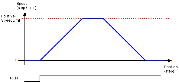
Move object 1000 steps in the positive direction with two speeds:
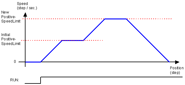
Before starting the motor the SetPoint must be set to a position 1000 higher than the current position.
Start the motor and wait for the motor to reach the initial speed limit. (Due to the speed deviation, a constant has to be subtracted from the speed limit before comparison). Then increase the speed limit and wait for the movement to finish.
PD626.Stepper.Setpoint := PD626.Stepper.ActualPosition + 1000;
PD626.Stepper.Enable[Run] := True;
While PD626.Stepper.ActualSpeed < PD626.Stepper.PositiveSpeedLimit-X Do ChangeTask;
PD626.Stepper.PositiveSpeedLimit := NewSpeed;
Repeat ChangeTask Until PD626.Stepper.InFlag[MotorIdle];
Move to base position:
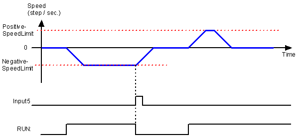
Base in this example, is defined as the point where the sensor connected to Input5 raises the signal.
The motor is set to run in a negative direction until the Input5 sensor is reached. The distance to Input5 is unknown, but this system has a maximum move length of 50000 steps, so Input5 must be found within this distance. When Input5 is reached, the Run flag is automatically reset. The motor ramps down and stops. When stopped, the trigger position is copied to SetPoint and the stepper moves up to this position. This position is then defined as 0.
PD626.Stepper.Setpoint := -50000; (* set maximum distance *)
PD626.Stepper.Input5Function.StopOnRiseEdge := True;
PD626.Stepper.Enable[Run] := True;
Repeat ChangeTask Until PD626.Stepper.InFlag[MotorIdle];
PD626.Stepper.SetPoint := PD626.Stepper.Input5Capture.LastRisePosition;
PD626.Stepper.Enable[Run] := True;
Repeat ChangeTask Until PD626.Stepper.InFlag[MotorIdle];
PD626.Stepper.Enable[Run] := False;
PD626.Stepper.SetPoint := 0;
PD626.Stepper.ActualPosition := 0;
Move between several positions
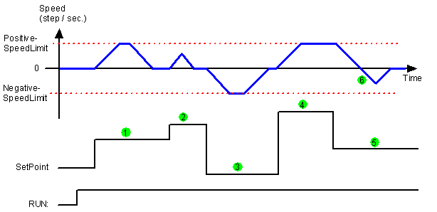
Activate the RUN flag. Enter SetPoint (1). The stepper accelerates and limits the speed to PositiveSpeedLimit. When stopped, the SetPoint is increased with a small number of steps (2). The motor accelerates but never reaches the speed limit and decelerates to stop at the requested position.
SetPoint is decreased (3) and the motor accelerates in a negative direction and runs at the NegativeSpeedLimit. SetPoint is increased (4) and the stepper moves forward. The SetPoint is decreased (5) before the final position is reached. The motor decelerates and stops beyond the new requested position. To reach the position, the stepper now reverses the movement (6) to return to the SetPoint position.
PD626.Stepper.Enable[Run] := True;
PD626.Stepper.SetPoint := PD626.Stepper.SetPoint + 1000; (* 1 *)
Repeat ChangeTask Until PD626.Stepper.InFlag[MotorIdle];
PD626.Stepper.SetPoint := PD626.Stepper.SetPoint + 20; (* 2 *)
Repeat ChangeTask Until PD626.Stepper.InFlag[MotorIdle];
PD626.Stepper.SetPoint := PD626.Stepper.SetPoint – 1500; (* 3 *)
Repeat ChangeTask Until PD626.Stepper.InFlag[MotorIdle];
PD626.Stepper.SetPoint := PD626.Stepper.SetPoint + 1900; (* 4 *)
While PD626.Stepper.ActualPosition < PD626.Stepper.SetPoint – 200 Do ChangeTask;
PD626.Stepper.SetPoint := PD626.Stepper.SetPoint – 1500; (* 5 *)
While PD626.Stepper.ActualPosition <> PD626.Stepper.SetPoint Do ChangeTask;
Position variables
Step figures and position counters in the PD 626 are always LongIntegers (32 bit integers).
A LongInteger can be assigned the value from -231 to + 231-1. Step values are treated as circular numbers, where any position value can be increased or decreased by 231. This means that wherever the stepper motor has finished the movement, a new movement can span +/- 2 billion steps relative to the current position, even if it crosses 0 or crosses the maximum point of the positive and negative number.
The stepper motor will always move the shortest distance between two points, so it can never move more than 231 in one operation (~2 billion steps), in a single position operation.
231 = 2,147,483,648, which for simplicity is rounded to 2 billion.
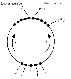
The maximum step rate of the PD 626 is 13,000 step / second. At this speed the stepper can run for 165,191 seconds = 45 hours within the 2 billion steps.
If the stepper motor runs in speed mode for a long time, the CurrentPosition will “roll over” and continue counting.


