PRODUCT DESCRIPTION
The BM 010 base provides connections for devices with one P-NET RS485 channel, or with two independent P-NET RS485 channels.
Please note the following: When BM 010 is used with devices with one P-NET RS485 channel, only the terminals marked A1, B1 and S1 must be used. The terminals marked A2, B2 and S2 are reserved for RS485 P-NET channel 2 on devices having two P-NET RS485 channels (PD 662).
The Base Modules are snap-locked directly on a DIN-Rail and interlocks with neighboring modules to ensure stability.
The Terminal Base Module has two terminals for all the channels for connection to the process signals, respecting the demand for only one wire in each terminal, ensuring a safe and straight forward design- and installation process. One of the two terminals is with the negative supply and the other is the input / output terminal. Having only one wire in each terminal enables that the wiring to/from process signals can be done directly, without the need for any further intermediate terminals.
The Terminal Base provides also a power rail for connections to the power supply, as well as guides for the Light-Link interface.
Cable termination circuit
The BM 010 base module is equipped with termination circuits for the two P‑NET channels.
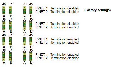
It is recommended to enable the termination circuit when the device is installed at the terminal ends of a transmission cable. Enabling/disabling the termination circuit is done via jumper settings.
Termination enabled:
When termination is enabled for P-NET 1 or P-NET 2 the terminals 2,6,10 and 4,8,12 are disconnected respectively.
This ensures that the termination can only be selected at the end devices.
Termination disabled:
The bus is internally looped through from the first to the second terminal set. This implies that incoming and outgoing P-NET cables have individual terminals.
 Jumper location
The jumpers used to enable/disable the termination circuits are found on the printed circuit board inside the BM 010, as seen on the picture.
J7 & J8: P-NET 1
J5 & J6: P-NET 2
Jumper settings
SPECIFICATIONS
Connector:
Max. wire-dimension: 2,2 mm2
Cage clamp opening size: 2.5 x 1.7 mm
Contact resistance: <15 mohm
Power Specifications
Current supplied by power rail Max. 10 A
Ambient Temperature
Operating temperature: -25 °C – 70 °C
Storage temperature: -40 °C – 85 °C
Humidity
Relative humidity: Max. 95%
Vibration approval
Standard: IEC 60068-2-6
Frequency range: 2-100 Hz
Frequency / amplitude: 2-10 Hz: +/- 5.0 mm, 10-100 Hz: +/- 2g
Sweep rate: Max. 1 octave/min.
Number of axes: 3 mutually perpendicular